Fuel cell technology is actually an “old hat”. The first fuel cell was developed by Sir William Grove in 1839; the first fuel cell stack was already introduced to the public in 1842 . Nevertheless, the innovative electro-chemical concept initially gathered dust in the drawer – it was defeated by the petrol engine which had also just been invented. Science had indeed progressed sufficiently in the 19th century to solve the problems related with converting chemical into mechanical energy. The foundation for an understanding of electro-chemical processes on an atomic level as required for fuel cell technology, however, was not laid before the development of the first electron microscope. Over the past three decades, the fuel cell has developed into a serious technology, though, and it is tipped as a major element of renewable energy supplies for the 21st century.
The principle of a fuel cell is very much the same as that of a battery, i.e. it comprises two electrodes – anode and cathode – as well as the electrolyte which separates the reactions spatially and forces the current flow through an external conductor. In contrast to a battery which is used up in operation, however, a fuel cell is continuously supplied with fuels. In the simplest case, hydrogen is oxidised into protons on the anode. These protons migrate to the cathode side through the proton-conductive membrane, while the electrons flow through the outer current circuit. On the cathode, oxygen is reduced and combines with the electrons and protons. The resulting products are water and electricity.
The electrode reactions described do not take place voluntarily, though; they require a so-called catalyst, which is platinum in the simplest case. Unfortunately, platinum is not only characterized by catalytic activity and long-term stability, but it is also a very expensive precious metal. For this reason, it is not used as a solid metal sheet, but in the form of supported and unsupported nanoparticles. Given the same quantity, their surface contributing to reaction surpasses that of sheet material many times over. For instance, 25 grams of a carbon-supported catalyst have the surface area of a soccer field, i.e. a total surface area of 7,140 m², or 300 m² per gram (fig. 1).
Looking into, learning and understanding
Research in the Renewable Energies Department of the Technische Universität Darmstadt aims at creating an optimum catalyst system. This system should not only be efficient and solid, but also non-toxic and of course cost-efficient. “Looking into, learning and understanding” is decisive for the development of customized catalysts. Understanding the action mechanism of a catalyst in-situ, for instance, requires an approach that delivers this information without affecting the reaction process. Consequently our group elaborated an approach which allows the examination of the catalyst while it is active in the fuel cell. This approach is based on X-ray absorption spectroscopy (EXAFS) and is particularly eligible for in-situ investigations since neither ultra-high vacuum is required during measurement, nor is short-range order needed within the sample. This means, measurements can easily be made within the fuel cell during operation, even on nanoparticles. The only disadvantage of this method is that it cannot be set up in the laboratory, but only in specialized large research facilities, so-called synchrotron laboratories, to which users from all over the world have access (Fig. 2) .
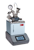
Measurement requires adjustable X-ray radiation whose energy is within the range of the absorption edges of the element to be investigated. Let us assume that the catalyst used in the fuel cell is a carbon-supported platinum system. In this case, the energy value of the applied radiation must exceed 11,000 eV in order to be absorbed by the platinum at its absorption edge. The absorption measurement in dependency of the energy of the applied X-ray radiation delivers information on the structure of the platinum nanoparticles, e.g. their size and whether they are heavily oxidised. In order for a measurement to be possible during operation , the X-rays must be capable of radiating through the cell. For this purpose, two windows must be provided in the in-situ cell first; however they do not have to be made of glass. Contrary to visible light, X-rays also largely radiate through carbon, beryllium and polyimide. Figure 2 (centre) shows a “transparent” fuel cell in which the catalyst may be examined under conditions as prevail during real operation.
In the experiment, absorption spectra are now recorded at various operation points in order to obtain information on the active catalyst’s behaviour. An appropriate evaluation of the data requires a large number of complex analysis steps and allows for determining the type, number and the distance of the nearest neighbouring atoms to an absorber atom. This is the basis for a nanoparticle structure model. A schematic diagram for a carbon-supported bi-metal catalyst is shown in figure 3. Blue balls represent platinum atoms, green balls symbolize metal ruthenium atoms, and oxidised ruthenium is shown in yellow. Approximately only 200 atoms are contained in a 2 nm (1 nm = billionth metre) large nanoparticle, and over 50 % of these atoms are located on the particle surface. This is what usually makes them available for the reaction.
Unlike materials on an ordinary scale, nanoparticles change their structure very easily under variable conditions. The changes in an operating catalyst are best illustrated in a cartoon (fig. 3): Before its application in the fuel cell, it is heavily oxidised. Precious platinum remains in the nanoparticle core, while a large portion of the ruthenium covers the particle surface as ruthenium oxide. As soon as the catalyst is activated in the fuel cell, a spontaneous structural change occurs upon the first contact with the fuel gas. The ruthenium oxide shell is reduced and ruthenium atoms slowly immigrate to the platinum core of the particle. The result is a more homogeneous distribution of platinum and ruthenium within the nanoparticle.
On track to sustainable technologies
The results of the active catalyst investigation are the first step towards customized catalyst systems. For only when we have understood the behaviour of a catalyst in
the fuel cell, can a system adapted to the operation conditions be established. The “transparent” fuel cell consequently represents a significant step towards environment-sparing and sustainable technologies. It contributes to gaining detailed knowledge used for the improvement of applied catalyst systems. This will save costs and eventually help conserve resources.
Header image: iStock.com | ipopba
First publication:
Roth, C.,
q&more,
1.2011.